 |
 |
|
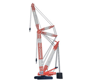
QUY70 Crawler Crane Main features High cost-performance and outstanding lifting capacity: leading the trade and exceeding your imagination! 1. The control system applied to this type of crane is an electronic management system, which adopts CAN bus technology, has intelligent fault diagnosis function and is equipped with intelligent color display. 2. The pendant plate made of high-strength plate, which has taken the place of traditional wire rope, has the advantages of excellent rigidity, light weight, great load-bearing capacity and low wind drag etc. 3. The crane is equipped with a self-assembly/dismantling system. No auxiliary crane is required for loading, unloading, assembly and dismantling. 4. The actuating time of brakes and the opening time of valves fitted in winch mechanisms can be adjusted freely to optimum matching state. The applied advanced PLC controller can make every speed parameter be adjusted within specified range in accordance with the user's habit, which embodies the ergonomic design of our crane. 5. The closed slewing mechanism has controllable free swing function which can reduce the impacts on the crane and ensure that superstructure starts/stops slewing more stably. The internal slewing ring and slewing reducer with great load-bearing capacity and high precision can ensure stable and precise slewing motion. 6. The traveling mechanism can make the crane have high maneuverability and perform such motions as traveling in straight line, one-side crawler steering, differential steering and turning on the spot as well as traveling with load. 7. The main pump control system, which has the functions of advanced load feedback and electrically-controlled power adjustment, makes the crane have good jogging performance so as to satisfy the demands in different working conditions required by customers. |
|
QUY70 Crawler Crane Main Technical Specifications |
Item |
Value |
Remarks |
|||
Max. lifting capacity ¡Á Radius |
t ¡Á m |
70¡Á3.8 |
|
||
Deadweight with basic boom |
t |
61 |
|
||
Main boom length |
m |
12~57 |
|
||
Fixed jib length |
m |
6~18 |
|
||
Max. lifting capacity of fixed jib |
t |
6.4 |
|
||
Offset angle of fixed jib |
¡ã |
10,30 |
|
||
Max. length of main boom with fixed jib |
m |
42 £« 18 |
|
||
Max. speed of single rope on drum |
Main winch |
m/min |
120 |
The 4 th rope layer |
|
Auxiliary winch |
m/min |
120 |
The 4 th rope layer |
||
Derricking winch |
m/min |
45 |
The 4 th rope layer |
||
Slewing speed |
rpm |
0~2.4 |
|
||
Traveling speed |
km/h |
0~1.35 |
|
||
Gradeability |
£¥ |
30 |
|
||
Ground pressure |
MPa |
0.074 |
|
||
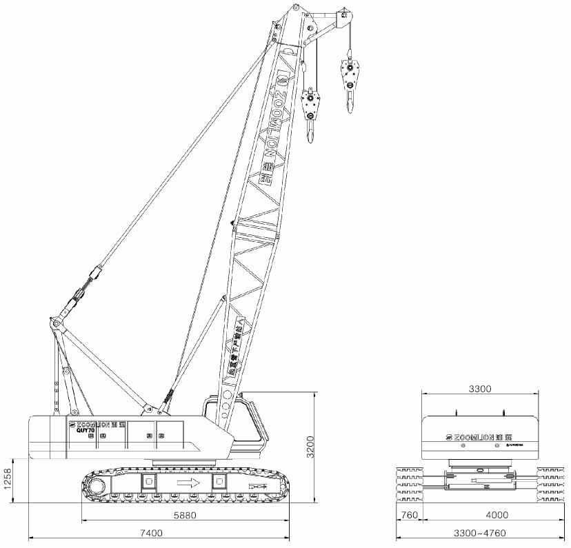
Overall dimensions (L¡ÁW¡ÁH) |
m |
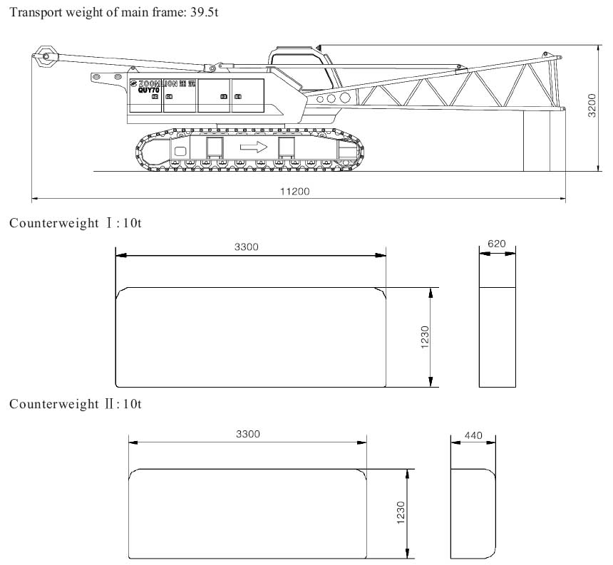
11.2¡Á3.3¡Á3.2 |
Mast and foot section are included |
||
Engine |
Rated power/ rotational speed |
kW/rpm |
153/2200 |
|
|
Max. output torque/ rotational speed |
Nm/rpm |
929/1300 |
|
||
Emission standard |
TIER 3 |
|
|||
Crawler gauge ¡Á ground contact length ¡Á track shoe width |
mm |
2540¡Á5040¡Á1000 |
Track bracket retracts |
||
mm |
4000¡Á5040¡Á1000 |
Track bracket retracts |
|||
|
Outline dimension and weight of main transport components |
 |
|
Technical instruction |
1.Boom system |
|
It is lattice structure and made of domestic high-strength tubular
product Main boom Main boom length:12 57m Adjusting lengthened boom section length for main boom: 3m, 6m, or 9m Fixed fly jib Fixed fly jib length:6 18m Adjusting lengthened boom section length for fixed fly jib: 6m Main boom+ longest fixed fly jib length: 42+18m |
2.Mechanisms |
|
Main hoist mechanism |
| It consists of axial concealed plunger hydraulic motor, balanced
valve, reducer, normally closed brake and wire rope. It is
independent of other mechanisms to be operated. It is two-speed type, having two different lifting speeds, which can improve working efficiency. |
Auxiliary hoist mechanism |
| It consists of axial concealed plunger hydraulic motor, balance
valve, reducer, normally closed brake and wire rope. It is
independent of other mechanisms to be operated . It is two-speed type, having two different lifting speeds, which can improve working efficiency. |
Boom hoist mechanism |
| It consists of axial concealed plunger hydraulic motor, balance
valve, reducer, normally closed brake, pulley block and wire rope. It is independent of other mechanisms to be operated. It is also equipped with ratchet self-locking protecting mechanism which can prevent luffing gear from slipping because of long time parking. |
Slewing gear |
| It consists of axial concealed plunger hydraulic motor, gear
reducer, slewing brake valve, brake, pinion gear and slewing ring. The superstructure can realize 360 slewing via slewing ring which is driven by pinion gear. The mechanism adopts internal-geared slewing ring and slewing reducer. Its great carrying capacity and high accuracy ensure the stability and accuracy of slewing. Slewing can realize stepless-speed regulation varying from 0 to 2.4r/min. The slewing gear can be locked by two mechanical locking devices in the front of the slewing table. |
Traveling mechanism |
| Traveling mechanism adopts double-motor and double-reducer. Hydraulic motor and balanced valve are all imported from Germany. Two sets of control levers respectively control two tracks traveling to realize straight-line traveling, one-sided steering, differential steering, spot turn and traveling with load etc. and then ensure the crawler crane have great mobility and flexibility. Traveling speed 0 1.35km/h( when ground is level and firm and main boom length is 20m without load). Gradeability 30 . Tension degree of track can be changed by jack. It is very quick, convenient and reliable. |
Mast mechanism |
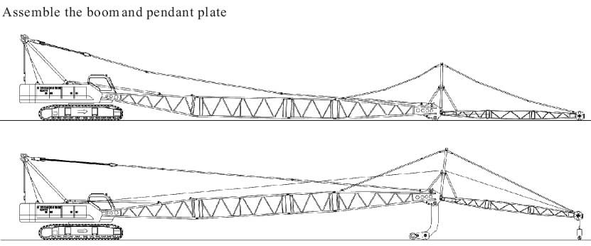
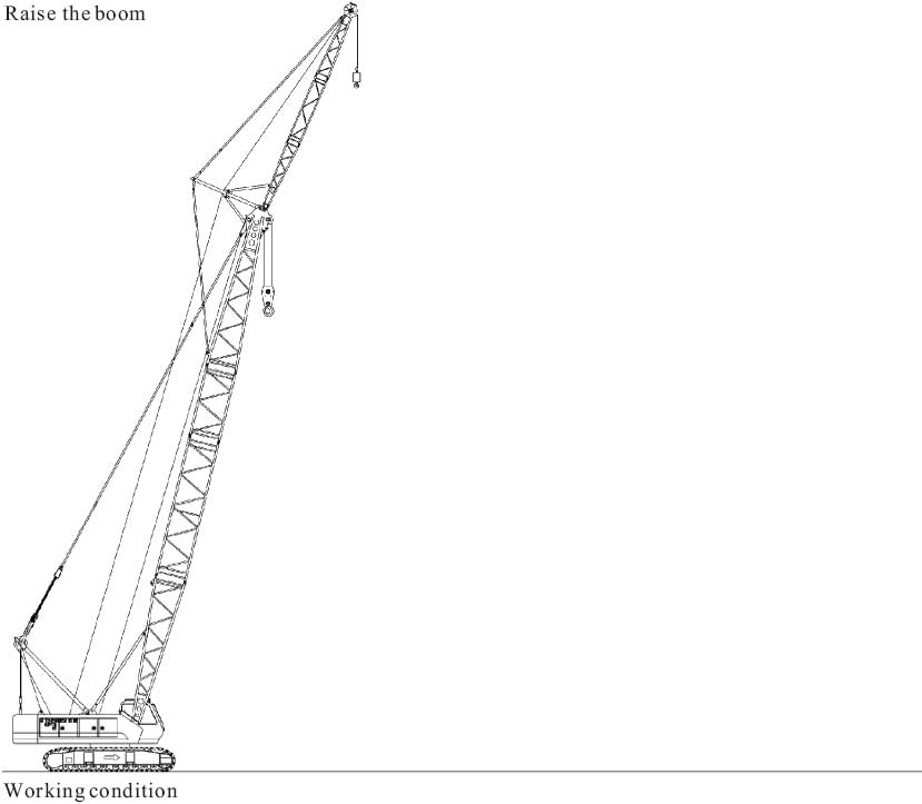
| It consists of mast, pendant plate of mast selfassembly/dismantling pendant plate etc.. it is used for selfassembly/dismantling of the crane. Before doing this work, the
mast should be turned back to connect the pendant plate and
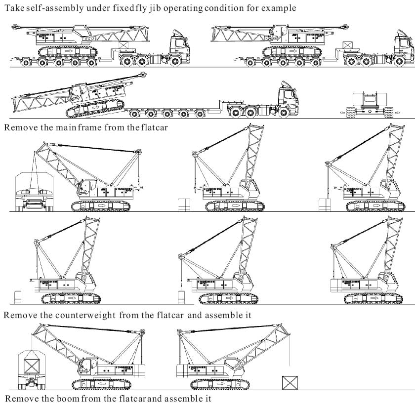
disassemble and assemble the counterweight. When the crane is traveling, the mast is laid flat on the rear side of slewing table. Counterweight and its assembly/dismantling mechanism It consists of two pieces of counterweight, mounting pin of counterweight, fixing bolt etc... QUY70 crawler crane can realize self-assembly/dismantling of counterweigh. |
Track telescoping mechanism |
| Track telescoping and operating mechanism consists of outriggers,
horizontal cylinders, track, pendant plate, and inserted pin etc... The telescoping of outriggers can be carried out by operating the control lever in the straight front of the vehicle frame. |
3.Systems |
Hydraulic system |
| Hydraulic system consists of main pump, control valve, hydraulic
motor, hydraulic oil tank and condenser etc... Hydraulic system adopts advanced pump control system in the world and its main components such as motor are all imported and have advantages of high efficiency, energy-saving, high reliability and long service life. Main hydraulic pump: domestic plunger pump, driven by engine. Oil source of auxiliary mechanism: gear pump. Main control valve: pilot electrohydraulic control valve Control method of main loop: the variable quantity of variable main pump+ main reversing valve, both controlled by the two operating handles. Hydraulic oil tank capacity: 700L. Cooler: aluminium radiator with electric fan. |
Electrical system |
| This system with 24V DC and earth negative, has two 195 AH
accumulators. Electric appliance of complete vehicle mainly include power,engine start, engine shutdown, indicator lamp, annunciator, illumination, fan, wiper, horn, lifting height limiter, hydraulic oil cooling fan, digitized display, PLC controller, preheating device for engine and safety equipment etc., which ensure safe operation and excellent working environment of the crane. The complete vehicle adopts CAN-bus technology, which connects the engine, PLC controller and digitized display efficiently, and has trouble detecting and self-diagnosis function. |
Power system |
| Weichai engine, in-line six cylinder, supercharge, water-cooling
engine Rated power/rotational speed: 175kw/2200r/min Fuel tank capacity: is 300L which ensures that the working hour of engine is long enough. Emission standard: meets the requirement of GB3847-1999 and GB17691-2001 stage . It can select to assemble imported CUMMINS engine QSB6.7-C205, America. |
Centralized display system |
| 11 inch large LCD intercalates Multilanguage display and can centralized display kinds of working condition signals collected by PLC controller, including rotational speed of engine, water temperature, fuel oil pressure, hydraulic pump pressure, main motor pressure and main frame working level circs etc. it can monitor working states in real time and give a yellow or red warning when the working state of crane is abnormal. |
4.Safety equipment |
| Load moment limiter |
| It consists of load moment display and digital LCD. When actual
load moment reaches 90% of rated moment, the warning lamp is
on and the buzzer alarms; when it nearly reaches the rated load
moment, the crane stops working automatically to prevent
accidents occur during operation because of overload and ensure
normal and safe work. Digital LCD displays following data: Moment ratio Elevation angle of main boom Main boom length Working radius Actual load Permissible lifting load Max. permissible lifting height Overflow valves of hydraulic system It can restrain the abnormal high pressure in loop to prevent hydraulic oil pump and hydraulic motor from damage and prevent hydraulic system from overload. Hoisting limiter Prevent hook from excessive lifting and avoid accidents occurring. Boom angle indicator It is mounted at the lower rear side of foot section (namely the right side of operator s cab). The driver can observe the elevation angle of boom clearly from the cab. Limit position alarm system for actuating arm The system can ensure that the actuating arm angle is within the specified range. Level sensor of the complete vehicle Detect the level state of the complete vehicle. Anti-unhook device Prevent load fall off from the hook when lifting. Ratchet locking mechanism of luffing gear Prevent luffing gear from sliding down because of long time parking. Overwind and overrelease protection device for wire rope Anemoscope |
5.Operator s cab |
It adopts all-steel structure. The four sides are all made of
hardened glass, and the roof and the front window are furnished with laminated glass. It is equipped with right sun visor, adjustable seat, wiper, electric control lever, load moment display, digitized displayer, auxiliary remote-control box operation assembly of switches, air conditioner, electric fan, illumination lamp, radio, cigarette lighter, fire extinguisher etc. inside. It also supplies wide vision and spacious and comfortable inner room for operator. |
6.Hook |
| Following types of hook can be selected to assemble: 70t main hook: assembled 6 sheaves 30t hook: assembled 2 sheaves 6t hook: without sheave |
|
Entire self-assembly/dismantling function |
 |
 |
 |
|
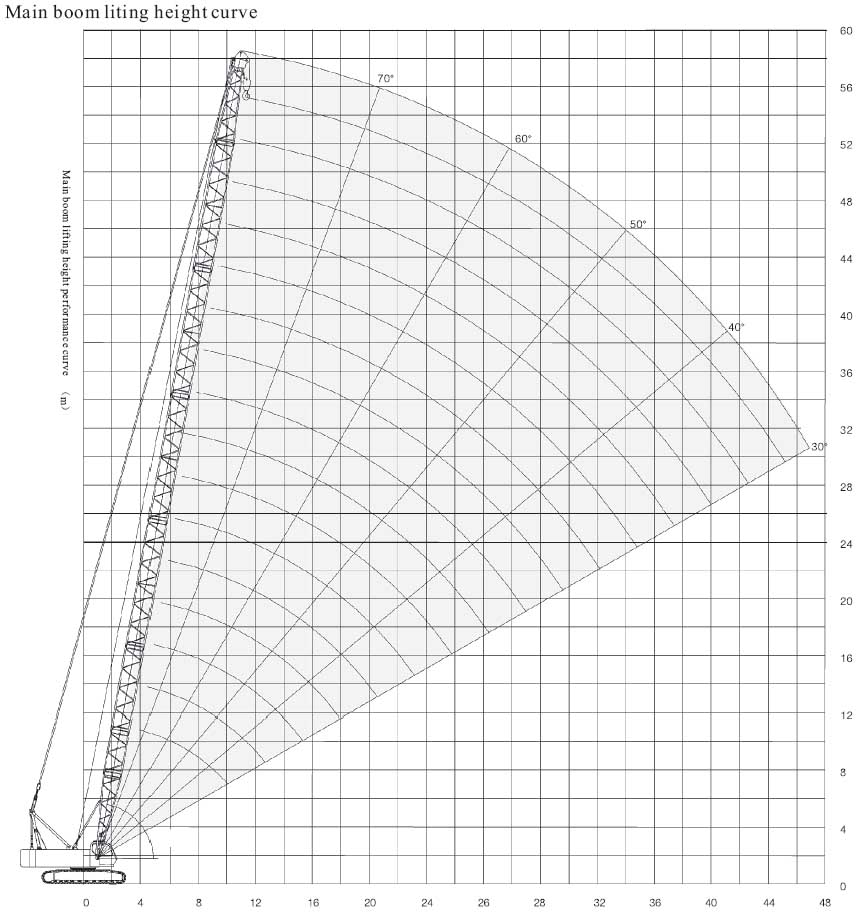
Main boom lifting performance |
 |
|
Main boom load rating chart(1) |
Main boom length |
12 |
15 |
18 |
21 |
24 |
27 |
30 |
33 |
Number of lines |
12 |
12 |
10 |
8 |
8 |
6 |
6 |
6 |
Working radius |
||||||||
3.8 |
70 |
|||||||
4 |
65 |
65 |
58.2/4.1 |
51.2/4.6 |
||||
5 |
53.6 |
52.3 |
51 |
49.8 |
44.2/5.2 |
37/5.7 |
||
6 |
40.5 |
40.1 |
39.3 |
38.5 |
37.7 |
36.9 |
34/6.2 |
30.4/6.7 |
7 |
32.1 |
32 |
31.8 |
31.2 |
30.6 |
30.1 |
29.5 |
28.9 |
8 |
26.6 |
26.5 |
26.4 |
26.2 |
25.8 |
25.3 |
24.8 |
24.3 |
9 |
22.6 |
22.5 |
22.4 |
22.3 |
22.2 |
21.8 |
21.4 |
21 |
10 |
19.7 |
19.5 |
19.4 |
19.3 |
19.2 |
19.1 |
18.7 |
18.4 |
12 |
15.4 |
15.3 |
15.1 |
15 |
14.9 |
14.8 |
14.6 |
|
14 |
12.6 |
12.5 |
12.4 |
12.2 |
12.1 |
12 |
11.9 |
|
16 |
10.5 |
10.4 |
10.2 |
10.1 |
10 |
9.9 |
||
19 |
8.3 |
8.1 |
8 |
7.9 |
7.8 |
|||
20 |
7.6 |
7.5 |
7.3 |
7.2 |
||||
22 |
6.7 |
6.5 |
6.4 |
6.3 |
||||
24 |
5.8 |
5.7 |
5.5 |
|||||
26 |
5 |
4.9 |
||||||
28 |
4.4 |
|||||||
29 |
4.1 |
|||||||
| Notes: 1.Values in load rating chart include the weight of hook, wire rope between head of boom and hook. 2.When lift load with runner, the lifting load is the same as that of main boom of the same length at the same working radius, but its max. lifting load should be no more than 6.4t. |
||||||||
|
Main boom load rating chart(2) |
Main boom length |
36 |
39 |
42 |
45 |
48 |
51 |
54 |
57 |
Number of lines |
4 |
4 |
4 |
3 |
3 |
3 |
3 |
3 |
Working radius |
||||||||
7 |
27.1/7.3 |
24.3/7.8 |
||||||
8 |
23.9 |
23.4 |
21.9/8.3 |
19.9/8.8 |
||||
9 |
20.6 |
20.2 |
19.8 |
19.4 |
18.1/9.3 |
14.6/9.9 |
||
10 |
18 |
17.7 |
17.3 |
17 |
16.6 |
14.6 |
14.6/10.4 |
13.7/10.9 |
12 |
14.3 |
14 |
13.7 |
13.5 |
13.2 |
13.3 |
13.1 |
12.8 |
14 |
11.7 |
11.5 |
11.3 |
11 |
10.8 |
10.9 |
10.7 |
10.5 |
16 |
9.8 |
9.6 |
9.5 |
9.2 |
9 |
9.1 |
8.9 |
8.7 |
19 |
7.6 |
7.5 |
7.4 |
7.3 |
7.7 |
7 |
6.9 |
6.8 |
20 |
7.1 |
7 |
6.8 |
6.7 |
7.1 |
6.5 |
6.3 |
6.2 |
22 |
6.2 |
6 |
5.9 |
5.8 |
6.6 |
5.5 |
5.4 |
5.3 |
24 |
5.4 |
5.3 |
5.1 |
5 |
5.7 |
4.8 |
4.6 |
4.5 |
26 |
4.8 |
4.6 |
4.5 |
4.4 |
4.9 |
4.1 |
4 |
3.9 |
28 |
4.2 |
4.1 |
4 |
3.9 |
4.3 |
3.6 |
3.5 |
3.3 |
29 |
4 |
3.9 |
3.7 |
3.6 |
3.7 |
3.4 |
3.2 |
3.1 |
30 |
3.8 |
3.6 |
3.5 |
3.4 |
3.5 |
3.1 |
3 |
2.9 |
32 |
3.4 |
3.2 |
3.1 |
3 |
3.3 |
2.7 |
2.6 |
2.5 |
34 |
2.9 |
2.8 |
2.6 |
2.9 |
2.4 |
2.3 |
2.1 |
|
36 |
2.5 |
2.3 |
2.5 |
2.1 |
1.9 |
1.8 |
||
37 |
2.3 |
2.2 |
2.2 |
1.9 |
1.8 |
1.7 |
||
38 |
2.1 |
2.1 |
1.8 |
1.7 |
1.5 |
|||
39 |
1.9 |
1.9 |
1.7 |
1.5 |
1.4 |
|||
40 |
1.8 |
1.6 |
1.4 |
1.3 |
||||
42 |
1.7 |
1.3 |
1.2 |
1.1 |
||||
|
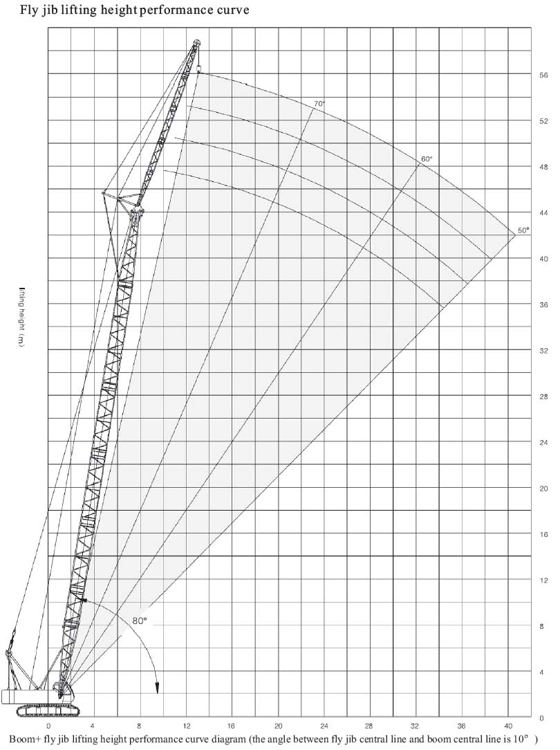
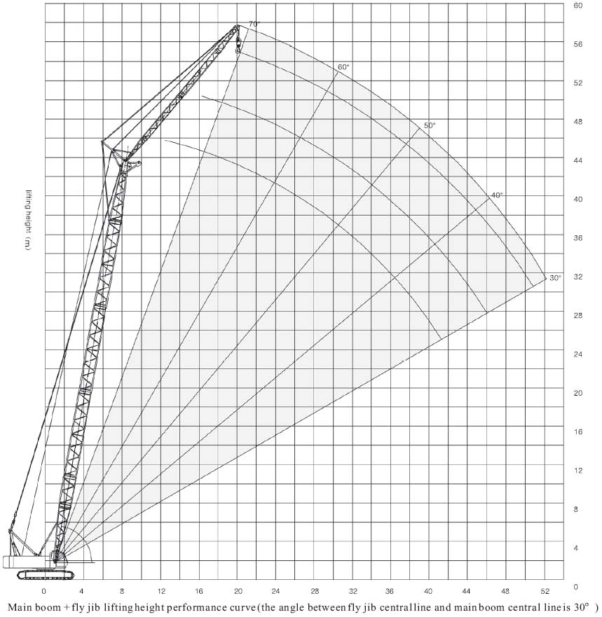
Fly jib lifting performance |
 |
 |
|
Fly jib load rating chart |
main boom length |
30 |
33 |
||||||||||
fly jib length |
6 |
12
|
18
|
6
|
12
|
18
|
||||||
working radius |
10¡ã |
30¡ã |
10¡ã |
30¡ã |
10¡ã |
30¡ã |
10¡ã |
30¡ã |
10¡ã |
30¡ã |
10¡ã |
30¡ã |
8 |
6.4/8.3 |
6.4/8.8 |
||||||||||
10 |
6.4 |
6.4/10.1 |
6.4/10.3 |
6.4 |
6.4/10.6 |
6.4/10.8 |
||||||
12 |
6.4 |
6.4 |
6.4 |
6.4/13.9 |
5.0/12.4 |
6.4 |
6.4 |
6.4 |
4.9/12.9 |
|||
14 |
6.4 |
6.4 |
6.4 |
6.4 |
4.8 |
6.4 |
6.4 |
6.4 |
6.4/14.4 |
4.9 |
||
16 |
6.4 |
6.4 |
6.4 |
6.4 |
4.8 |
4.5/17.8 |
6.4 |
6.4 |
6.4 |
6.4 |
4.8 |
|
18 |
6.4 |
6.4 |
6.4 |
6.4 |
4.7 |
4.5 |
6.4 |
6.4 |
6.4 |
6.4 |
4.8 |
4.4/18.3 |
20 |
6.4 |
6.4 |
6.4 |
6.4 |
4.6 |
4.3 |
6.4 |
6.4 |
6.4 |
6.4 |
4.6 |
4.3 |
22 |
6.4 |
6.4 |
6.4 |
6.4 |
4.5 |
4.3 |
6.3 |
6.3 |
6.4 |
6.4 |
4.5 |
4.3 |
24 |
5.6 |
5.6 |
5.9 |
5.9 |
4.5 |
4.3 |
5.5 |
5.5 |
5.6 |
5.8 |
4.5 |
4.3 |
26 |
4.9 |
4.9 |
5.2 |
5.2 |
4.4 |
4.2 |
4.8 |
4.8 |
5 |
5.1 |
4.5 |
4.2 |
28 |
4.4 |
4.4 |
4.6 |
4.6 |
4.4 |
4.2 |
4.3 |
4.3 |
4.4 |
4.5 |
4.4 |
4.2 |
30 |
3.9 |
3.9 |
4.1 |
4.1 |
4.2 |
4.2 |
3.8 |
3.8 |
3.9 |
4.0 |
4 |
4.2 |
32 |
3.5 |
3.5 |
3.7 |
3.7 |
3.6 |
3.9 |
3.4 |
3.4 |
3.5 |
3.6 |
3.6 |
3.8 |
34 |
3.3 |
3.3 |
3.4 |
3.5 |
3.0 |
3.0 |
3.2 |
3.2 |
3.3 |
3.4 |
||
36 |
3 |
3 |
3.1 |
3.1 |
2.6 |
2.6 |
2.9 |
2.9 |
2.9 |
3.0 |
||
38 |
2.6 |
2.6 |
2.8 |
2.8 |
2.5 |
2.5 |
2.6 |
2.7 |
||||
40 |
2.5 |
2.5 |
2.3 |
2.3 |
2.4 |
2.4 |
||||||
42 |
2.3 |
2.3 |
2.0 |
2.0 |
2.2 |
2.2 |
||||||
44 |
2.0 |
2.0 |
1.9 |
1.9 |
||||||||
main boom length |
36 |
39
|
42 |
|||||||||||||||
fly jib length |
6 |
12
|
18
|
6
|
12
|
18
|
6 |
12 |
18 |
|||||||||
working radius |
10¡ã |
30¡ã |
10¡ã |
30¡ã |
10¡ã |
30¡ã |
10¡ã |
30¡ã |
10¡ã |
30¡ã |
10¡ã |
30¡ã |
10¡ã |
30¡ã |
10¡ã |
30¡ã |
10¡ã |
30¡ã |
8 |
6.4/ 9.3 |
6.4/9.8 |
6.4/ 11.9 |
|||||||||||||||
10 |
6.4 |
6.4/ 11.1 |
6.4/ 11.4 |
6.4 |
6.4/ 11.6 6.4 |
6.4 |
6.4/ 10.3 |
|||||||||||
12 |
6.4 |
6.4 |
6.4 |
4.9/ 13.4 |
6.4 |
6.4 |
6.4 |
4.9/ 13.9 |
6.4 |
6.4/ 12.2 |
6.4/ 12.4 |
|||||||
14 |
6.4 |
6.4 |
6.4 |
6.4/ 15 |
4.9 |
6.4 |
6.4 |
6.4 |
6.4/ 15.5 |
4.9 |
6.4 |
6.4 |
6.4 |
4.9/ 14.4 |
||||
16 |
6.4 |
6.4 |
6.4 |
6.4 |
4.8 |
6.4 |
6.4 |
6.4 |
6.4 |
4.8 |
6.4 |
6.4 |
6.4 |
6.4 |
4.9 |
|||
18 |
6.4 |
6.4 |
6.4 |
6.4 |
4.8 |
4.5/ 18.8 |
6.4 |
6.4 |
6.4 |
6.4 |
4.8 |
4.5/ |
6.4 |
6.4 |
6.4 |
6.4 |
4.8 |
4.5/19.9 |
20 |
6.4 |
6.4 |
6.4 |
6.4 |
4.7 |
4.4 |
6.4 |
6.4 |
6.4 |
6.4 |
4.7 |
4.5 |
6.4 |
6.4 |
6.4 |
6.4 |
4.7 |
4.5 |
22 |
6.1 |
6.2 |
6.3 |
6.4 |
4.5 |
4.3 |
6 |
6.1 |
6.2 |
6.4 |
4.6 |
4.3 |
5.9 |
6.1 |
6.1 |
6.3 |
4.7 |
4.3 |
24 |
5.3 |
5.4 |
5.5 |
5.7 |
4.5 |
4.3 |
5.2 |
5.3 |
5.4 |
5.6 |
4.6 |
4.3 |
5.1 |
5.2 |
5.3 |
5.5 |
4.6 |
4.3 |
26 |
4.7 |
4.7 |
4.9 |
5.0 |
4.5 |
4.3 |
4.6 |
4.6 |
4.7 |
4.9 |
4.5 |
4.3 |
4.4 |
4.5 |
4.6 |
4.8 |
4.6 |
4.3 |
28 |
4.1 |
4.1 |
4.3 |
4.4 |
4.3 |
4.2 |
4 |
4.0 |
4.2 |
4.3 |
4.2 |
4.2 |
3.9 |
4 |
4.1 |
4.2 |
4.2 |
4.3 |
30 |
3.7 |
3.7 |
3.8 |
3.9 |
3.9 |
4.1 |
3.5 |
3.5 |
3.7 |
3.8 |
3.8 |
4.0 |
3.4 |
3.4 |
3.6 |
3.7 |
3.7 |
3.9 |
32 |
3.2 |
3.2 |
3.4 |
3.5 |
3.5 |
3.7 |
3.1 |
3.1 |
3.3 |
3.4 |
3.4 |
3.6 |
3 |
3.0 |
3.2 |
3.3 |
3.3 |
3.3 |
34 |
2.9 |
2.9 |
3 |
3.1 |
3.1 |
3.3 |
2.8 |
2.8 |
2.9 |
3.0 |
3 |
3.2 |
2.6 |
2.6 |
2.8 |
2.9 |
2.9 |
3.1 |
36 |
2.5 |
2.5 |
2.7 |
2.8 |
2.8 |
2.9 |
2.4 |
2.4 |
2.6 |
2.6 |
2.7 |
2.8 |
2.3 |
2.3 |
2.5 |
2.5 |
2.6 |
2.7 |
38 |
2.2 |
2.2 |
2.4 |
2.4 |
2.5 |
2.6 |
2.1 |
2.1 |
2.3 |
2.3 |
2.4 |
2.5 |
2.1 |
2.0 |
2.2 |
2.2 |
2.3 |
2.4 |
40 |
2.2 |
2.2 |
2.3 |
2.3 |
1.9 |
1.9 |
2.1 |
2.1 |
2.1 |
2.2 |
1.8 |
1.8 |
1.9 |
2.0 |
2 |
2.1 |
||
42 |
2 |
2 |
2 |
2.1 |
1.6 |
1.6 |
1.8 |
1.8 |
1.9 |
2.0 |
1.5 |
1.5 |
1.7 |
1.7 |
1.8 |
1.9 |
||
44 |
1.7 |
1.7 |
1.8 |
1.8 |
1.6 |
1.6 |
1.7 |
1.8 |
1.3 |
1.3 |
1.5 |
1.5 |
1.6 |
1.7 |
||||
46 |
1.6 |
1.6 |
1.4 |
1.4 |
1.5 |
1.5 |
1.3 |
1.3 |
1.4 |
1.4 |
||||||||
48 |
1.4 |
1.4 |
1.3 |
1.3 |
1.1 |
1.1 |
1.2 |
1.2 |
||||||||||
50 |
1.2 |
1.2 |
1.2 |
1.2 |
1.1 |
1.1 |
||||||||||||
52 |
1 |
1.0 |
0.9 |
0.9 |
||||||||||||||
54 |
0.8 |
0.8 |
||||||||||||||||
| Note: All specifications on our web-site are subject to technical modifications without notice. |
| Download Infomation |